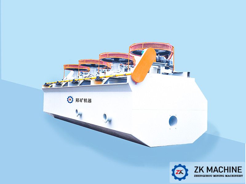
The BF-type mineral processing flotation machine features a structure with a closed double-stage conical impeller, capable of drawing in sufficient air and slurry. Our company offers twelve models of BF-type flotation machines with tank volumes ranging from 0.37 to 24 m³, production capacities of 0.2–24 m³/min, and installed power of 1.5–45 kW.
The BF-type flotation machine is an upgraded new-generation flotation device based on the SF-type flotation machine. It is a structurally innovative self-aspirated flotation machine, offering advantages such as horizontal configuration, automatic return of middling froth, and self-aspiration of air. Additionally, it boasts low power consumption, high air intake, low impeller linear speed, extended wear-resistant component lifespan, and stable pulp level.
✔ Applications
Scope: Suitable for separating non-ferrous metals, ferrous metals, non-metallic minerals, and chemical raw materials, as well as recovering valuable minerals.
✔ Key Advantages
The BF-type flotation machine's impeller consists of a closed double truncated cone, generating strong downward slurry circulation. Its features include:
1. High air intake with low power consumption.
2. Each tank integrates three functions—air suction, slurry suction, and flotation—forming an independent flotation circuit without auxiliary equipment. Its horizontal configuration allows easy process adjustments.
3. Rational slurry circulation minimizes coarse sand sedimentation.
4. Equipped with automatic or electric control devices for pulp level adjustment, ensuring convenient operation.
✔ Working Principle
When the main shaft, driven by the motor, rotates the impeller, the slurry in the impeller chamber is thrown outward by centrifugal force, creating negative pressure that draws air through the suction pipe. Simultaneously, slurry below the impeller is sucked into the impeller chamber through the central hole of the lower conical disc, where it mixes with air. The mixture is then discharged through the channels between the cover plate blades. Part of the air and slurry rises to the upper part of the flotation tank, forming froth that overflows into the next tank for further separation, while the remaining slurry moves downward and is re-sucked into the impeller chamber, creating downward slurry circulation. This circulation helps suspend coarse particles, reducing sedimentation at the tank bottom.


